One
Overview
This board is based on our successful Autonomo, a proven 32 bits Arduino compatible platform. It has a solar charge controller and runs on a LiPo or permanent battery.
Next we added a GPS module. We chose the U-blox Eva 7M/8M/M8M. It’s not only very small, but with it’s assisted GPS feature it can get a fix in just seconds.
We also included a low power Accelerometer/Magnetometer chip. This means we can keep the board in sleep until it moves or has a change in magnetic field. This is crucial for developing low power devices.
Say you want to develop a bicycle tracker. You would like know the position of the bike, but only when it has moved. So keep the device in deep sleep until you detect motion. If the motion continues for a while, the bicycle may have changed position so you only then switch on the GPS to get a new reading and send this new location over the LoRa network. This way you make most efficient use of you battery capacity by only using the GPS when really needed.
The Magnetometer extends the range of possibilities. You could now use the board to develop a parking sensor (fit the device in the street, if a car is parked this changes the magnetic field). Or you can mount it to a fence and use the compass direction to determine if the gate is open or not.
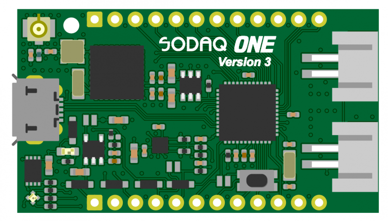
The board is so small (45×25 mm) you can fit it inside almost anything. To ease the development we have fitted two rows of headers so you can use it on a breadboard. Why? Well it has 14 free I/O lines that you can use for your own purpose. Whether you want to build a weather station, control street lights or get a signal when you have received (snail) mail. It’s all possible with the SODAQ ONE.
The SODAQ ONE RN2483(868Mhz) and RN2903(915Mhz) are available in our shop.
Note
The SODAQ ONE is a development/evaluation tool intended for the evaluation of Microchip wireless modules in a Research and Development laboratory environment. It is not a Finished Appliance. Manufacturers who integrate SODAQ ONE in a Finished Appliance must take responsibility to follow regulatory guidelines, for example for CE marking.
Warning
- Do not short circuit any of the pins of the SODAQ ONE because of risk of heat, smoke, and fire.
- Take appropriate precautions while handling the PCB assembly because of exposed components.
- Do not alter the device into regulatory non-compliant modes.
Getting Started
Follow the getting started guide to verify you use the correct URL and update your boardfiles to the latest version.
Features
| Microcontroller | ATSAMD21G18, 32-Bit ARM Cortex M0+ |
| Compatibility | Arduino M0 Compatible |
| Size | 40 x 25 mm (v1 and v2), 45 x 25 mm (v3) |
| Operating Voltage | 3.3V |
| I/O Pins | 14, All can be used for digital and analog with PWM, UART, SPI and TWI (I2C) |
| Analog Output Pin | 10-bit DAC |
| External Interrupts | Available on all pins |
| DC Current per I/O pin | 7 mA |
| Flash Memory | 256 KB |
| SRAM | 32KB |
| EEPROM | Up to 16KB by emulation |
| Clock Speed | 48 MHz |
| Power | 5V USB power and/or 3.7 LiPo battery |
| Charging | Solar charge controller, up to 500mA charge current |
| LED | RGB LED |
| LoRa | Microchip RN2483 or RN2903 Module |
| GPS | uBlox EVA 7M (v1) / uBlox EVA 8M (v2 and v3) / uBlox EVA M8M (v3) |
| Accelerometer/Magneto | LSM303D(v1) / LIS3DE(v2) / LSM303AGR (v3) |
| USB | MicroUSB Port |
v1 vs v2 vs v3
One v2
The components we use to make the ONE v2 are more power efficient.
The GPS module we updates from the U-blox EVA 7M to the U-blox EVA 8M. The accelerometer/magnetometer has been replaced by an accelerometer which can be used in a very low power mode and wake up the board by an interrupt.
The RF path is shorter, this results in better antenna performance. To make the RF path shorter we have removed the line for the 2nd frequency, we don’t support the 433Mhz anymore.
We added a LoRa reset line from the microcontroller to the RN module. If the RN module isn’t responding anymore, the microcontroller can do a hard reset to the RN module.
One v3 changelog
- Added CE logo
- Added pull-down on GPS_ENABLE pin
- Added solder jumper to connect/disconnect regulator output (default: connected)
- Added solder jumper to enable/disable regulator enable pin (default: enabled)
- Added solder jumper to enable/disable reset button (default: enabled)
- Changed accelerometer to LSM303AGR
- The user button is now changed to be a reset button
- Moved LoRa U.FL connector to bottom side of PCB
Later we also updated the GPS from the 8M to the M8M.
Summary
The SODAQ ONE, ONE v2 and ONE v3 are pin compatible! We made Universal Tracker software is for the V1, V2 and V3.
| ONE | ONE v2 | One v3 |
|---|---|---|
| GPS EVA 7M | GPS EVA 8M | GPS EVA 8M / GNSS EVA M8M |
| LoRa 868/433 or 915 | LoRa 868 or 915 | LoRa 868 or 915 |
| Accelerometer and Magnetometer (LSM303D) | Low power accelerometer with interrupt lines (LIS3DE) | Accelerometer and Magnetometer (LSM303AGR) |
| No lora reset line | LoRa reset line | LoRa reset line |
| User Button | User Button | Reset Button |
Pinout
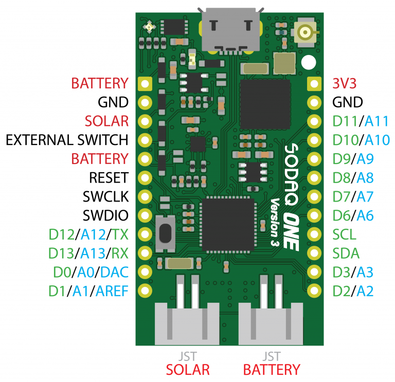
Pin definitions
Now that you’re using the SODAQ ONE board files, you’ll be able to use our handy pin definitions. Let’s say you want to use the red LED, but you forgot that pesky pin number, you can just address the led with LED_RED inside your Arduino IDE. Our pin definitions allow you to address by name instead of pin number.
Here are all the pin definitions for the SODAQ ONE:
| Pin description | Pin number | Definition |
|---|---|---|
| Red LED | D14 | LED_RED |
| Green LED | D15 | LED_GREEN |
| Blue LED | D16 | LED_BLUE |
| Power Enable | D22 | ENABLE_PIN_IO |
| GPS Enable | D18 | GPS_ENABLE |
| External Switch Sense | D23 | SWITCH_SENSE |
| Push Button | D19 | BUTTON |
| GPS Timepulse | D17 | GPS_TIMEPULSE |
| MISO (SPI) | D8* | MISO |
| SS (SPI) | D9* | SS |
| MOSI (SPI) | D10* | MOSI |
| SCK (SPI) | D11* | SCK |
SPI pinout for the Sodaq One Beta: D4: MISO, D5: SS, D6: MOSI, D7: SCK
Hardware Serials
The SODAQ One has 3 hardware serials:
SerialUSB – This is for when you are debugging over the USB Cable.
Serial – Serial is attached to pin D12/TX and D13/RX.
Serial1 – Is connected to the RN2XX3 LoRaWAN Module.
void setup() {
  // put your setup code here, to run once:
  SerialUSB.begin(57600);
  Serial.begin(57600);
  Serial1.begin(57600);
}

void loop() {
  // put your main code here, to run repeatedly:

}
Schematics
- SODAQ One Beta, Rev. 2 schematic
- SODAQ One Rev.3
- SODAQ One Rev.4
- SODAQ One V2 Schematic
- SODAQ One Base V2 Schematic